
Resistance: Principles and Calculations
Resistance: Principles and Calculations
Resistance is a fundamental concept in electrical theory that refers to the opposition that a material offers to the flow of electric current. It is a key factor in determining how electrical circuits operate and how much current will flow through a given part of the circuit. The unit of resistance is the ohm (Ω), and it is symbolized by the Greek letter R in formulas.
This section will provide a detailed explanation of the principles of resistance, the formula used to calculate resistance, and three examples of how to apply these calculations in practical situations. Relevant sections from BS 7671, Guidance Note 3, and the On-Site Guide will also be referenced.
1. What is Resistance?
Resistance occurs because the atoms in a conductor impede the flow of electrons (current). The higher the resistance in a conductor, the lower the current flow for a given voltage. This concept is essential in electrical installations, as resistive components are used to control current, prevent overloading, and distribute power effectively across circuits.
Materials with low resistance (such as copper) allow current to flow easily, while materials with high resistance (such as rubber) restrict the flow of current. This is why copper is commonly used for electrical wiring, and rubber is used for insulation.
The resistance of a conductor depends on several factors:
- Material: Conductors like copper and aluminum have low resistance, while insulators like rubber have high resistance.
- Length of the conductor: Resistance increases with the length of the conductor.
- Cross-sectional area: Resistance decreases as the cross-sectional area of the conductor increases.
- Temperature: As the temperature of most conductors increases, their resistance also increases.
Reference:
- BS 7671, Section 132 (Design).
- Guidance Note 3, Chapter 2 (Electrical Theory).
- On-Site Guide, Section 10 (Testing and Inspection).

3. Factors Affecting Resistance
The resistance of a conductor is affected by four key factors: the material, length, cross-sectional area, and temperature.
- Material: Different materials have different resistivities, which determine how much they resist the flow of current.
- Length of Conductor: The longer the conductor, the higher the resistance.
- Cross-Sectional Area: A conductor with a larger cross-sectional area has lower resistance because more electrons can flow through the conductor at the same time.
- Temperature: Most materials increase their resistance as the temperature rises. This is particularly important for electrical installations where conductors may heat up under load.

4. Practical Application of Resistance in Electrical Installations
In real-world electrical installations, resistance is important when sizing cables and ensuring the efficiency and safety of circuits. For example, high resistance in a conductor can lead to significant voltage drops, which can reduce the performance of connected devices or cause overheating.
The total resistance of a circuit, especially for long runs of cable, can also affect the earth fault loop impedance (Zs), which in turn influences the disconnection times of protective devices.
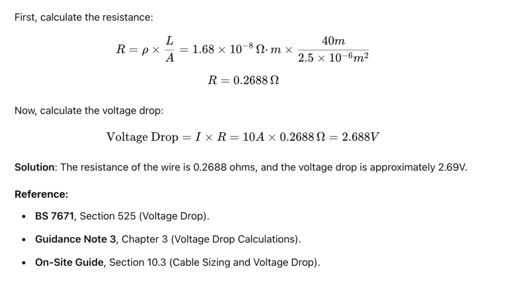
Example 3: Resistance and Voltage Drop in a Circuit
Scenario:
An electrician is wiring a 40-meter-long circuit using copper wire with a cross-sectional area of 2.5 mm². The resistivity of copper is 1.68×10⁻⁸ Ω⋅m1.68 \times 10^{-8} \, \Omega·m1.68×10−8Ω⋅m. Calculate the resistance of the wire and the voltage drop for a 10A load on a 230V supply.
5. Measurement of Resistance in Testing
Measuring the resistance of circuits and components is a fundamental part of inspection and testing in electrical installations. The most common method is using a continuity tester or a multifunction tester to measure the resistance of protective conductors, which ensures that they are correctly connected and provide the necessary protection.
Key Testing Applications:
- Continuity of Protective Conductors (R1 + R2): Ensures that the earth path is continuous and that all exposed conductive parts are effectively earthed.
- Insulation Resistance Testing: Confirms that the insulation between conductors and between conductors and earth is sufficient to prevent leakage currents.
Summary Table of References
| Topic | BS 7671 Reference | Guidance Note 3 Reference | On-Site Guide Reference |
|---|---|---|---|
| Principles of Resistance | Section 132 (Design) | Chapter 2 (Electrical Theory) | Section 10 (Testing and Inspection) |
| Resistance Formula (Ohm’s Law) | Section 525 (Voltage Drop) | Chapter 3 (Voltage Drop) | Section 10.3 (Voltage Drop) |
| Measurement of Resistance | Section 643 (Inspection and Testing) | Chapters 2–3 (Continuity and Resistance Testing) | Section 10.3 (Resistance Testing) |
Summary
Resistance is a key concept in electrical theory, affecting everything from the performance of circuits to the safety of an electrical installation. Understanding how to calculate resistance using Ohm’s Law and other formulas is essential for electricians to size cables, prevent voltage drops, and ensure that circuits function efficiently. Electrical testing methods, such as continuity testing and insulation resistance testing, rely on measuring resistance to ensure the safety and compliance of the installation with BS 7671.